Michael Opdenacker is the founder of Bootlin, and was its CEO until 2021. He is best known for all the free embedded Linux and kernel training materials that he created together with Thomas Petazzoni.
He is always looking for ways to increase performance,
reduce size and boot time, and to maximize Linux' world domination. More details...
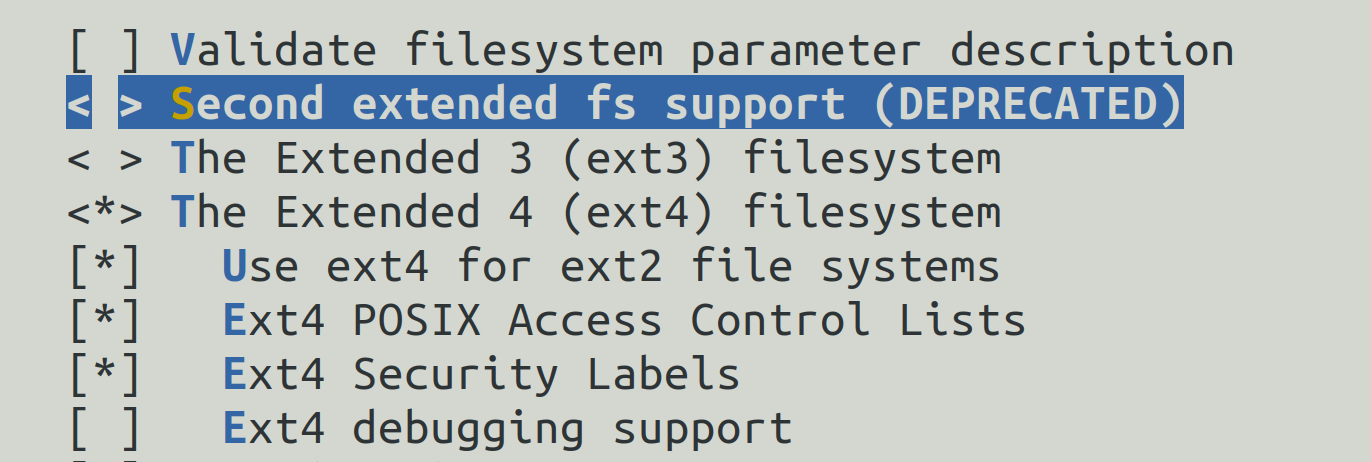
31 years after the start of its career in 1993, it’s time for ext2 to retire. Here we are talking about the driver for this filesystem, not exactly the filesystem itself. Continue reading to understand the subtle difference.
It’s the ext2 filesystem driver that will be marked as deprecated in the upcoming 6.9 Linux kernel. The main issue is that even if the filesystem is created with 256 byte inodes (mkfs.ext2 -I 256), the filesystem driver will stick to 32 bit dates. Because of this, the driver does not support inode timestamps beyond 03:14:07 UTC on 19 January 2038.
The Yocto Project has published its new release: 4.2, also known as “Mickledore”.
It features improved Rust support, BitBake engine improvements, support for Linux 6.1 (the latest Long Term Support kernel), new QEMU features, testing improvements and of course many other new features and package updates. See the release notes for all details.
When the compressed and uncompressed kernel images overlap
At least on ARM32, there seems to be many working addresses where the compressed kernel can be loaded in RAM. For example, one can load the compressed kernel at offset 0x1000000 (16 MB) from the start of RAM, and the Device Tree Blog (DTB) at offset 0x2000000 (32 MB). Whatever this loading address, the kernel is then decompressed at offset 0x8000 from the start of RAM, as explained this the famous How the ARM32 Linux kernel decompresses article from Linus Walleij.
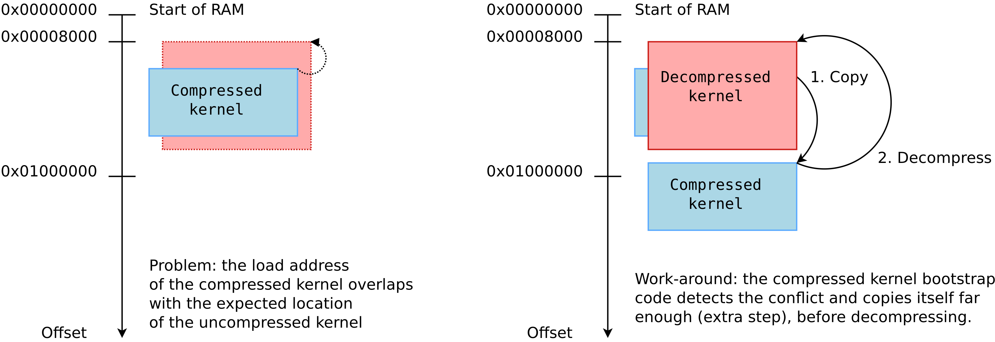
There is a potential issue with the loading address of the compressed kernel, as explained in the article too. If the compressed kernel is loaded too close to the beginning of RAM, where the kernel must be decompressed, there will be an overlap between the two. The decompressed kernel will overwrite the compressed one, potentially breaking the decompression process.
As you see in the above diagram, when this happens, the bootstrap code in the compressed kernel will first copy the compressed image to a location that’s far enough to guarantee that the decompressed kernel won’t overlap it. However, this extra step in the boot process has a cost.
0xc0000000 is exactly the beginning of RAM! We are therefore in the overlap situation.
We used grabserial from Tim Bird to measure the time between Starting kernel in U-Boot and when the compressed kernel starts executing (Booting Linux on physical CPU 0x0):
...
[4.451996 0.000124] Starting kernel ...
[0.001838 0.001838]
[2.439980 2.438142] [    0.000000] Booting Linux on physical CPU 0x0
...
On a series of 5 identical tests, we obtained an average time of 2,440 ms, with a standard deviation of 0.4 ms.
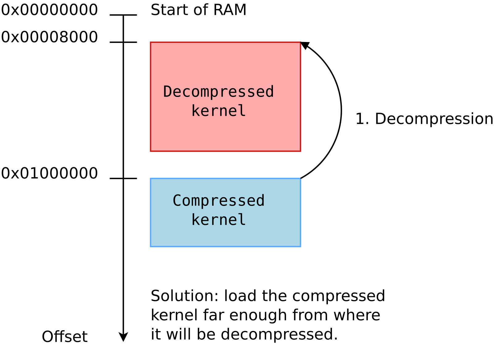
Then, we measured the optimum case, in which the compressed kernel is loaded far enough from the beginning of RAM so that no overlap is possible:
On a series of 5 identical tests, we obtained an average time of 2,333 ms, with a standard deviation of 0.7 ms.
The new average is 107 ms smaller, which you are likely to consider as a worthy reduction, if you have experience with boot time reduction projects.
What to remember
In your embedded projects, if you are using a compressed kernel, make sure it is loaded far enough from the beginning of RAM, leaving enough space for the decompressed kernel to fit in between. Otherwise, your system will still be able to boot, but depending on the speed of your CPU and storage, it will be slower, from a few tens to a few hundreds of milliseconds.
We checked the How to optimize the boot time page on the STM32 wiki, and it recommends optimum loading addresses: 0xc2000000 for the kernel and 0xc4000000 for the device tree. This way, the upper limit for the decompressed kernel is 32 MB, which is more than enough.
If you are directly using an uncompressed kernel, which is more rare, you should also make sure that it is loaded at an optimum location, so that there is no need to move it before starting it.
As every six months for the last two years, a new virtual edition of the Yocto Project Summit is coming, and its schedule has been announced.
This summit will be over 3 days:
Tuesday, November 29
Two tracks in parallel, a beginner track and a “hands-on” track for people already familiar with the concepts.
Wednesday, November 30
Only one track, with intermediate level talks on all kinds of topics.
Thursday, December 1
Only one track, starting with “product showcase” talks and going on with intermediate level talks on various topics too.
Last but not least, at the end of each day, you will get a chance to hangout with other contributors and users, and ask all the questions that you may have.
Bootlin is indeed involved in the Yocto Project by maintaining its documentation (see the active contributors through the git repository), and also a participant to the Yocto SWAT team, keeping track of all the issues encountered by the autobuilder machines and runs.
Though the Yocto Project and OpenEmbedded are Open Source projects, registration for this conference is not free but just costs 40 USD, to cover infrastructure and staffing costs, the event being hosted by the Linux Foundation.
On recent GNU/Linux distributions such as Ubuntu 22.04 and 22.10, you may hit an issue creating a bootable FAT partition for embedded boards, at least with the TI AM335x processor, such as the 32 bit Beagle Bone boards.
Here are the quickest instructions (I hope) for having the Yocto Project build an embedded Linux image for BeagleBone boards based on the TI AM335x CPU:
As explained in the first two blog posts, the BeagleBone boards are supported by a wide number of extension boards, called capes.
When such a cape is plugged in, the description of the devices connected to the board should be updated accordingly. As the available hardware is described by a Device Tree, the added devices on the cape should be described using a Device Tree Overlay, as described in the first blog post.
As explained in this post too, the bootloader is today’s standard place for loading Device Tree Overlays on top of the board’s Device Tree. Once you know which capes are plugged in, you can load them in U-Boot and boot Linux as in the following example:
This mechanism works fine, but every time you plug in a different cape, you have to tweak this sequence of commands to load the right overlay (the .dtbo file). This would be great if each cape could be detected automatically and so could be the corresponding overlays.
Actually, all this is possible and already supported in mainline U-Boot starting from version 2021.07. That’s what this article is about.
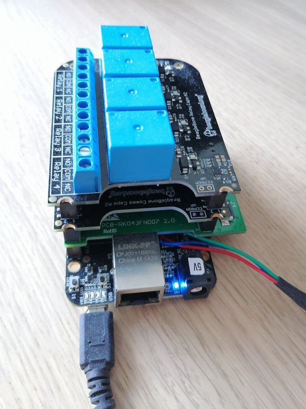
BeagleBone Black with multiple capes – We want to detect them automatically!
To identify which capes are plugged in, all you have to do is read the connected EEPROMs. You can test by yourself by booting a BeagleBone with a Debian image, and dumping the EEPROM contents as in the following example:
Of course, the above kind of command only works if the corresponding Device Tree Overlays are loaded. Otherwise, the Linux kernel won’t know that the I2C EEPROMs are available.
The U-Boot extension manager
In the latest Debian images proposed by BeagleBoard.org at the time of this writing, there is already a mechanism to detect the plugged capes based on the information on their I2C EEPROM. However, that was a custom mechanism, and BeagleBoard.org contracted Bootlin to implement a more generic mechanism in the official version of U-Boot.
This generic mechanism was implemented by my colleague Köry Maincent and added to U-Boot (since version 2021.07) by this commit.
Let’s test this mechanism by building and booting our own image. The following instructions apply to the BeagleBone Black board.
SD card preparation
Using cfdisk or a similar tool, prepare a micro-SD card with at least one partition which you mark as “Bootable”. Then format it with the FAT32 filesystem:
sudo mkfs.vfat -F 32 -n boot /dev/mmcblk0p1
Now, remove and plug the micro-SD card back in again. It should automatically be mounted on /media/$USER/boot.
Compiling U-Boot
We first need to install a cross-compiling toolchain if you don’t have one yet. Here’s how to do this on Ubuntu:
Then, let’s get the kernel sources and configure them:
git clone https://github.com/beagleboard/linux.git
cd linux
git checkout 5.10.100-ti-r40
export CROSS_COMPILE=arm-linux-gnueabihf-
export ARCH=arm
make omap2plus_defconfig
make menuconfig
In the configuration interface, enable compiling the Device Tree Overlays with CONFIG_OF_OVERLAY=y. Also set CONFIG_INITRAMFS_SOURCE="../rootfs.cpio". You can now compile the kernel and the Device Trees, and deploy them to the micro-SD card:
Configuring U-Boot and using the “extension” command
Now insert the micro-SD card in the BeagleBone Black. Connect the capes that you own. Then power on the board while holding the USR button (close to the USB host port).
On the serial line, you should see U-Boot 2022.04 starting. Interrupt the countdown by pressing any key, to access the U-Boot prompt:
U-Boot SPL 2022.04 (Apr 06 2022 - 15:04:53 +0200)
Trying to boot from MMC1


U-Boot 2022.04 (Apr 06 2022 - 15:04:53 +0200)

CPU  : AM335X-GP rev 2.1
Model: TI AM335x BeagleBone Black
DRAM:  512 MiB
Core:  150 devices, 14 uclasses, devicetree: separate
WDT:   Started wdt@44e35000 with servicing (60s timeout)
NAND:  0 MiB
MMC:   OMAP SD/MMC: 0, OMAP SD/MMC: 1
Loading Environment from FAT... Unable to read "uboot.env" from mmc0:1...
 not set. Validating first E-fuse MAC
Net:   eth2: ethernet@4a100000, eth3: usb_ether
Hit any key to stop autoboot:  0
=>
Let’s try the extension manager now. First, we load the kernel image and Device Tree Binary (DTB) for the board:
=> fatload mmc 0:1 0x81000000 zImage
6219488 bytes read in 408 ms (14.5 MiB/s)
=> fatload mmc 0:1 0x82000000 am335x-boneblack.dtb
64939 bytes read in 10 ms (6.2 MiB/s)
Then, we set the RAM address where each Device Tree Overlay will be loaded:
Taking the relay cape as an example, you can see that the name of the Device Tree overlay was derived from the description in its EEPROM, which we dumped earlier.
Now, everything’s ready to load the overlay for the first cape (number 0):
=> extension apply 0
loading BBORG_RELAY-00A2.dtbo
1716 bytes read in 5 ms (335 KiB/s)
Or for all capes:
=> extension apply all
loading BBORG_RELAY-00A2.dtbo
1716 bytes read in 5 ms (335 KiB/s)
loading BB-CAPE-DISP-CT4-00A0.dtbo
5372 bytes read in 5 ms (1 MiB/s)
loading BBORG_COMMS-00A2.dtbo
1492 bytes read in 4 ms (364.3 KiB/s)
We are now ready to set a generic command that will automatically load all the overlays for the supported capes, whatever they are, and then boot the Linux kernel:
6228224 bytes read in 526 ms (11.3 MiB/s)
93357 bytes read in 10 ms (8.9 MiB/s)
BeagleBone Cape: Relay Cape (0x54)
BeagleBone Cape: BB-CAPE-DISP-CT43 (0x55)
BeagleBone Cape: Industrial Comms Cape (0x56)
Found 3 extension board(s).
loading BBORG_RELAY-00A2.dtbo
1716 bytes read in 5 ms (335 KiB/s)
loading BB-CAPE-DISP-CT4-00A0.dtbo
5372 bytes read in 5 ms (1 MiB/s)
loading BBORG_COMMS-00A2.dtbo
1492 bytes read in 4 ms (364.3 KiB/s)
Kernel image @ 0x81000000 [ 0x000000 - 0x5f0900 ]
## Flattened Device Tree blob at 82000000
   Booting using the fdt blob at 0x82000000
   Loading Device Tree to 8ffe4000, end 8fffffff ... OK

Starting kernel ...

[    0.000000] Booting Linux on physical CPU 0x0
[    0.000000] Linux version 5.10.100 (mike@mike-laptop) (arm-linux-gnueabihf-gcc (Ubuntu 9.4.0-1ubuntu1~20.04.1) 9.4.0, GNU ld (GNU Binutils for Ubuntu) 2.34) #8 SMP Wed Apr 6 16:25:24 CEST 2022
...
To double check that the overlays were taken into account, you can log in a the root user (no password) and type this command:
# ls  /proc/device-tree/chosen/overlays/
BB-CAPE-DISP-CT4-00A0.kernel  BBORG_RELAY-00A2.kernel
BBORG_COMMS-00A2.kernel       name
Note: all the files used here, including the resulting U-Boot environment file, are available in this archive. All you have to do is extract the archive in a FAT partition with the bootable flag, and then you’ll be ready to boot your board with it, without any manipulation to perform in U-Boot.
How to add support for a new board
To prove that the new extension board manager in U-Boot was generic, Köry Maincent used it to support three different types of boards:
BeagleBone boards based on the AM3358 SoC from TI
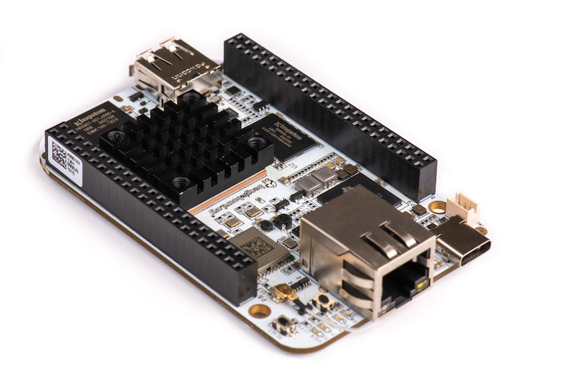
The BeagleBone AI board, based on the AM5729 SoC from TI
The CHIP computer, based on the Allwinner R8 CPU, and its DIP extension boards.
To support a new board and its extension boards, the main thing to implement is the extension_board_scan() function for your board.
A good example to check is this commit from Köry which introduced cape detection capabilities for the TI CPUs and this second commit that enabled the mechanism on AM57xx (BeagleBone AI). A good ideas is also to check the latest version of board/ti/common/cape_detect.c in U-Boot’s sources.
Summary
The U-Boot Extension Board Manager is a feature in U-Boot which allows to automatically detect extension boards, provided the hardware makes such a detection possible, and automatically load and apply the corresponding Device Tree overlays. It was contributed by Köry Maincent from Bootlin, thanks to funding from BeagleBoard.org.
At the time of this writing, this functionality is supported on the BeagleBone boards (AM335x and AM57xx), on the CHIP computer (Allwinner R8), and since more recently, on Compulab’s IOT-GATE-iMX8 gateways.
With the combination of this blog post and the former two (see the links at the beginning), it should be clear how a specification can be written to use a combination of Device Tree symbols, Udev rules and extension board identifiers to make expansion header hardware “just work” when plugged in to various boards with compatible headers. BeagleBoard.org would be proud if our example inspired other community board maintainers.
Bootlin would like to thank BeagleBoard.org for funding the development and deployment of this infrastructure in mainline U-Boot, and the creation of these three blog posts on Device Tree overlays.
Most of the BeagleBone boards from BeagleBoard.org share the same form factor, have the same headers and therefore can accept the same extension boards, also known as capes in the BeagleBoard world.
Of course, a careful PCB design was necessary to make this possible.
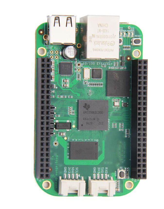
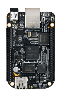
This must have been relatively easy with the early models (BeagleBone Black, Black Wireless, Green, Green Wireless, Black Industrial and Enhanced) which are based on the same Sitara AM3358 System on Chip (SoC) from Texas Instruments. However, the more recent creation of the BeagleBone AI board and keeping compatibility with existing capes must have been a little more complicated, as this board is based on a completely different SoC from Texas Instruments, the Sitara AM5729.
BeagleBone AI BeagleBone Green BeagleBone Black
Once the PCB design challenge was completed, the BeagleBoard.org crew set itself another challenge: implement software that supports each BeagleBone cape in the same way, whatever the board, in particular:
To have unique identifiers for devices in Linux, so that there is a stable name for Linux devices, even if at the hardware level they are connected differently, depending on whether the base board has a Sitara AM3358 and Sitara AM5729 SoC.
To have DT overlays for capes that are applicable to all base boards, even if peripherals are connected to different buses of the SoCs.
This article will explore the software solutions implemented by BeagleBoard.org. Their ideas can of course be reused by other projects with similar needs.
The need for a cape standard
A good summary can be found on Deepak Khatri’s Google Summer of Code 2020 page:
The idea of this project was to make the same user space examples work with both BeagleBone Black and BeagleBone AI, using the same references to drivers for peripherals assigned to the same pins between BeagleBone Black and BeagleBone AI. Also, Same DT overlays should work (whenever possible) for both BBB and BBAI, with updated U-Boot cape manager DT overlays will be automatically loaded during boot.
Software setup
The below instructions are for people owning the BeagleBone AI board and any other BeagleBone board, and interested in exploring the devices on their boards by themselves.
Uncompress each image, insert a micro-SD card in the card read in your PC, and then flash the corresponding card. Here are example commands, assuming that the micro-SD card is represented by the /dev/mmcblk0 device:
Connect the serial line of each board to your computer and then boot each board with it:
For BeagleBone AI: its sufficient to have the micro-SD card inserted.
On other BeagleBone boards, you may need to hold a button when you power up the board, to make it boot from the micro-SD card instead of from the internal eMMC. On the BeagleBone Black boards, for examples, that’s the USER button next to the USB host port. Note that you won’t need to do this again when you reset the board. The board will continue to boot from the external micro-SD card until it’s powered off.
You can connect with the default user, or connect as user root with password root.
Then, connect each board to the Internet, and get the latest package updates:
sudo apt update
sudo apt dist-upgrade
It’s then time to upgrade the kernel to the latest version supported by BeagleBoard. To do so, you’ll have to manually update the /opt/scripts/tools/update_kernel.sh file. In this file, go to the # parse commandline options section and add the below lines:
        --lts-5_10-kernel|--lts-5_10)
                kernel="LTS510"
                ;;
You can can then upgrade to the latest 5.10 kernel:
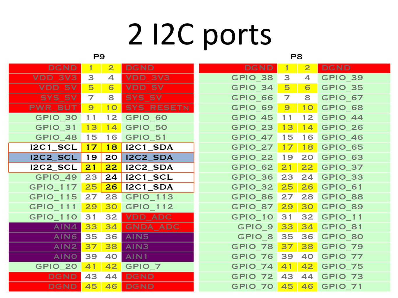
Note that on the BeagleBone Black, I2C1 and I2C2 are available at two different locations.
So, for both types of boards, we have at least I2C buses on P9_17/18, P9_19/20 and P9_24/26. However, that’s complicated because these pins don’t correspond to the same I2C buses. Therefore, users have to know that P9_19/20 correspond to I2C2 on BeagleBone Black and to I2C4 on BeagleBone AI.
The devices in /dev/ reflect such differences.
Here’s what we have on the BeagleBone AI:
root@beaglebone:~# ls -la /dev/i2c-*
crw------- 1 root root 89, 0 Mar 23 15:00 /dev/i2c-0
crw------- 1 root root 89, 3 Mar 23 15:00 /dev/i2c-3
Note that here with the AM5729 SoC, the first I2C bus is I2C1. Hence, /dev/i2c-0 corresponds to I2C1 (which is another I2C bus available on the SoC but not available through the cape headers) and /dev/i2c-3 corresponds to I2C4. Also note that I2C5 is not exposed in the default configuration that we have here, most probably because the corresponding header pins are used for other purposes.
And now let’s look at what we have on the BeagleBone Black:
root@beaglebone:~# ls -la /dev/i2c-*
crw------- 1 root root 89, 0 Mar 23 16:16 /dev/i2c-0
crw------- 1 root root 89, 1 Mar 23 16:17 /dev/i2c-1
crw------- 1 root root 89, 2 Mar 23 16:17 /dev/i2c-2
Here with the AM3358 SoC, /dev/i2c-0 corresponds to I2C0, /dev/ic2-1 to I2C1 and /dev/ic2-2 to I2C2.
So, on a running system, how to know which I2C bus device corresponds to the P9_19/20 header pins?
You can see that both devices, though they correspond to different devices, share the same symlink property, which is used to create a symbolic link in /dev/bone/i2c/ to the actual bus device file.
Let’s see such symbolic links on the BeagleBone AI:
root@beaglebone:~# ls -la /dev/bone/i2c/
total 0
drwxr-xr-x 2 root root 80 Jan  1  2000 .
drwxr-xr-x 4 root root 80 Jan  1  2000 ..
lrwxrwxrwx 1 root root 11 Mar 23 15:00 0 -> ../../i2c-0
lrwxrwxrwx 1 root root 11 Mar 23 15:00 2 -> ../../i2c-3
And on the BeagleBone Black:
root@beaglebone:~# ls -la /dev/bone/i2c/
total 0
drwxr-xr-x 2 root root 100 Mar 23 16:16 .
drwxr-xr-x 5 root root 100 Mar 23 16:16 ..
lrwxrwxrwx 1 root root  11 Mar 23 16:16 0 -> ../../i2c-0
lrwxrwxrwx 1 root root  11 Mar 23 16:17 1 -> ../../i2c-1
lrwxrwxrwx 1 root root  11 Mar 23 16:17 2 -> ../../i2c-2
You can see that at least /dev/bone/i2c/0 and /dev/bone/i2c/2 are shared between both types of boards. Userspace code examples can then support different boards by referring to such device file links, for example by using the I2C tools commands.
The symbolic links are created from the Device Tree sources not by the Linux kernel, but by the udev device manager, thanks to the following rule found in /etc/udev/rules.d/10-of-symlink.rules in the BeagleBoard Debian distribution:
# allow declaring a symlink for a device in DT

ATTR{device/of_node/symlink}!="", \
        ENV{OF_SYMLINK}="%s{device/of_node/symlink}"

ENV{OF_SYMLINK}!="", ENV{DEVNAME}!="", \
        SYMLINK+="%E{OF_SYMLINK}", \
        TAG+="systemd", ENV{SYSTEMD_ALIAS}+="/dev/%E{OF_SYMLINK}"
Accessing other devices
Other devices are available in the same way through symbolic links in /dev/bone/, for example UART (serial port) devices.
Let’s check on the BeagleBone AI (run sudo apt install tree first):
Another challenge is with userspace software examples directly refer to header pins by their names. Here is a BoneScript push button demo, for example:
var b = require('bonescript');
b.pinMode('P8_19', b.INPUT);
b.pinMode('P8_13', b.OUTPUT);
setInterval(check,100);

function check(){
b.digitalRead('P8_19', checkButton);
}

function checkButton(x) {
  if(x.value == 1){
    b.digitalWrite('P8_13', b.HIGH);
  }
  else{
    b.digitalWrite('P8_13', b.LOW);
  }
}
For AM3358 BeagleBone boards, the am335x-bone-common-univ.dtsi file already associates the P8_19 name to a specific GPIO:
However, this driver is specific to the BeagleBoard.org kernel, and the Device Tree for Beagle Bone AI doesn’t use it yet, so this aspect is still work in progress. The main goal remains though: define generic names for header pins, which map to specific GPIOs on different boards.
The goal as stated in the beginning is to use the same Device Tree overlays on both types of SoCs. While as of today it doesn’t seem possible to generate compiled Device Tree Overlays (DTBO) which would support both SoCs at the same time, the BeagleBoard.org engineers have come up with a solution to achieve this at source level. This means that, for each cape to support, the Device Tree Overlay binaries for the supported SoCs can be produced from a unique source file.
While this hasn’t been deployed yet in the 5.10 BeagleBoard kernel, such source code is already available in Deepak Khatri’s own tree.
/*
 * Copyright (C) 2020 Deepak Khatri
 *
 * Virtual cape for /dev/bone/can/1
 *
 * This program is free software; you can redistribute it and/or modify
 * it under the terms of the GNU General Public License version 2 as
 * published by the Free Software Foundation.
 */

/dts-v1/;
/plugin/;

/*
* Helper to show loaded overlays under: /proc/device-tree/chosen/overlays/
*/
&{/chosen} {
    overlays {
        BONE-CAN1 = __TIMESTAMP__;
    };
};

/*
 * Update the default pinmux of the pins.
 * See these files for the phandles (&P9_* & &P8_*)
 * https://github.com/lorforlinux/BeagleBoard-DeviceTrees/blob/compatibility/src/arm/am335x-bone-common-univ.dtsi
 * https://github.com/lorforlinux/BeagleBoard-DeviceTrees/blob/compatibility/src/arm/am572x-bone-common-univ.dtsi
 */
&ocp {
    P9_24_pinmux { pinctrl-0 = <&P9_24_can_pin>;};  /* can rx */
    P9_26_pinmux { pinctrl-0 = <&P9_26_can_pin>;};  /* can tx */
};

/*
 * See these files for the phandles (&bone_*) and other bone bus nodes
 * https://github.com/lorforlinux/BeagleBoard-DeviceTrees/blob/compatibility/src/arm/bbai-bone-buses.dtsi
 * https://github.com/lorforlinux/BeagleBoard-DeviceTrees/blob/compatibility/src/arm/bbb-bone-buses.dtsi
 */
&bone_can_1 {
    status = "okay";
};
The &ocp code applies the pin muxing definitions for CAN on P9_24 (&P9_24_can_pin) and P9_26 (&P9_26_can_pin), which of course are different on AM3358 and AM5729.
By adding a symlink property to the Device Tree sources, BeagleBoard.org has made it possible to make userspace code, in particular its code examples, support all the BeagleBone boards at the same time, even though the devices they drive have are numbered differently on different SoCs.
Such a technique may be reused by other projects interested in running the same software on boards based on different SoCs.
As far as GPIOs are concerned, the drivers/gpio/gpio-of-helper.c driver is specific to the BeagleBoard.org kernel and is unlikely to be accepted in the mainline kernel in its current state. However, there are other solutions, supported by the mainline kernel, to associate names to GPIOs and then to look up such GPIOs by name through libgpiod.
Last but not least, it’s possible to use the same Device Tree Overlay source code to support an extension board on similar boards, just by using common definitions having different values on each different platform. Any project can reuse this idea, which just uses standard Device Tree syntax.
Bootlin thanks BeagleBoard.org for funding the creation of this blog post. Note that another post is coming in the next weeks, about the extension board manager we added to U-Boot thanks to funding from BeagleBoard.org.
The Device Tree language is a way to describe hardware that is present in a system and cannot be automatically detected. That’s the case of devices directly implemented on a System on a Chip, such as serial ports, Ethernet or Nand flash controllers. That’s also the case of devices connected to a number of buses, such as I2C and SPI, that do not provide mechanisms for dynamic enumeration and identification of devices.
For a given CPU architecture (ARM, PowerPC, etc), such a description allows to have a unique kernel supporting many different systems with distinct Systems on a Chip. The compiled Device Tree (DTB: Device Tree Binary), passed to the kernel by the bootloader at boot time, lets the kernel know which SoC and devices to initialize. Therefore, when you create a new board, and want to use a standard GNU/Linux distribution on it, all you have to do is create a new Device Tree describing your new hardware, compile it, and boot the distribution’s kernel with it. You don’t need to recompile that kernel, at least when it supports your SoC and the devices on your board.
Kernel developers and board maintainers are not the only ones who may need to make changes to the board device trees, though. Normal users also have legitimate reasons for tweaking the device tree of their board, such as:
Declaring external devices connected to board connectors. The simplest example is an I2C temperature sensor, but this can also include entire expansion boards plugged into the main board.
Changing the hardware blocks that are exposed on the external pins of their System on Chip. This is called Pin Multiplexing, and the Device Tree is the place where such multiplexing is configured.
Modifying operating system related properties, such as the Linux kernel command line or flash partitions.
In you have such a need, a first way to do this would be to directly modify the Device Tree for your hardware in the kernel sources, and recompile it. However, this is a rather bad idea because it will make it more difficult to upgrade to a later version of the kernel, possibly featuring changes to the Device Tree file you modified too. It’s always better not to tweak files maintained by others, and find a way to override them instead.
A second possibility to tweak the Device Tree for a board is to include it from a custom Device Tree for your own use case, using the /include/ statement from the Device Tree language, or #include and the C preprocessor. You can then use references to nodes in the original tree, using labels, and then modify the properties of such nodes or add new subnodes to them. It’s even possible to remove existing nodes and properties by using the /delete-node/ and /delete-property/ statements, as shown in the Device Tree Source Undocumented page.
However, this is still an inconvenient solution. Any time you plug in a new device or an expansion board, or want to tweak other settings, you have to rebuild and update the full Device Tree for your board. What if you could prepare Device Tree fragments for each change to make, compile them once for all, and then, when you boot your device, load the main Device Tree and only the fragments you need, without having anything else to recompile?
This is exactly what Device Tree Overlays are about. For example, in /lib/firmware, the Debian image shipped by BeagleBoard.org contains compiled Device Tree Overlays (DTBO) for the extension boards (also known as capes in the BeagleBoard world) they support, such as:
Then, at boot time, all you have to do is load the main DTB for your board, and then override it using the DTBOs corresponding to the capes which are currently mounted. Kernel contributors have also worked on solutions to load the DTBOs dynamically in the live system, but this solution is not mature yet. Therefore, the bootloader based solution at boot time remains so far the best one.
Writing Device Tree overlays
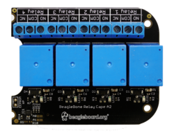
When the Device Tree overlays were first proposed, their syntax was very special and hard to remember. Fortunately, since version 1.5, the Device Tree compiler (dtc) supports a much more natural syntax for writing such overlays. For example, here are the sources for the overlay for the Relay cape, taken from the BBORG_RELAY-00A2.dts file in BeagleBoard.org’s Linux kernel tree:
BeagleBone Relay Cape
This example shows us what is specific to Device Tree Overlay source code, compared to the normal Device Tree syntax:
Before any definition, the code must include the /plugin/; statement.
As in normal Device Tree code, you can refer to labels (such as &am33xx_pinmux in the above example), modify their properties, add or remove nodes and properties.
However, you cannot modify nodes which do not have a label. In this case, you have to recall such nodes by describing their absolute path from the root device between curly braces. There are two such instances in the above code: &{/chosen} and &{/}.
Compiling Device Tree overlays
Once you have the source code of the your overlay, it is supposed to be easy to compile it with the Device Tree Compiler. This time, let’s take the example of the BBORG_FAN-A000.dts overlay for the Fan cape, slightly modified:
The only change we made to this file was to replace __TIMESTAMP__ by a real timestamp. This statement is actually a macro meant to be substituted by the C Preprocesor before compiling with dtc.
This is where real life Device Tree overlay examples are getting more difficult to compile. Very simple overlays can be compiled with the above command, but as soon as the code contains #include statements or macros to be substituted by the C preprocessor, you have to call this preprocessor and give it the path to where the corresponding .h files are found in the kernel sources.
Fortunately, the kernel Makefile knows a suitable series of commands to compile such overlay sources.
Let’s clone BeagleBoard.org’s Linux kernel source tree. It contains Device Tree Overlays for most capes that are compatible with BeagleBoarg.org’s boards, and if I understood correctly, BeagleBoard.org’s kernel developers haven’t solved all the conflicts between their definitions and recent kernels yet. So, let’s checkout their 5.10 branch:
git clone https://github.com/beagleboard/linux.git
cd linux
git branch -a
git checkout 5.10
First, let’s install a toolchain, for example the one on Ubuntu:
sudo apt install gcc-arm-linux-gnueabihf
And then let’s prepare the environment for compiling the kernel:
Then, we can configure the kernel for the OMAP SoCs:
make omap2plus_defconfig
We also need to tweak the configuration for compiling the Device Trees and Overlays properly. So, run make menuconfig and set CONFIG_OF_OVERLAY=y. For the practical manipulations, you will also need to set CONFIG_LEDS_GPIO=y and CONFIG_LEDS_CLASS=y.
Device Tree Overlays are found in arch/arm/boot/dts/overlays/. You can compile them along with all normal DTBs with:
make dtbs
In case you want to recompile a specific DT overlay, for example the BBORG_RELAY-00A2.dts file:
$ touch arch/arm/boot/dts/overlays/BBORG_RELAY-00A2.dts
$ make dtbs
  DTCO    arch/arm/boot/dts/overlays/BBORG_RELAY-00A2.dtbo
Of course, for any of this to be useful at the end, you will also need to compile the kernel:
make -j8 zImage
Applying Device Tree overlays
As we already explained, U-Boot is the place where the Device Tree Overlays should be applied. To do this, here are the commands to run in U-Boot. As an example, we’re using the BeagleBone Black and its Relay Cape as example, assuming all the files where copied to the first partition of a micro-SD card, containing a FAT filesystem:
Allocate extra space for the DTB for future overlays, here adding 8192 bytes for example:
fdt resize 8192
Apply the overlay that we just loaded to the main DTB:
fdt apply 0x83000000
We are then ready to load the Linux kernel and boot it. Let’s see a more complete example…
Example usage on BeagleBone Black
You can of course follow this example, but you can also test it by yourself if you own the BeagleBone Black (or similar BeagleBone boards), and its Relay Cape.
Board setup
First, connect the Relay Cape to your board. In the below example, more capes are actually stacked, the Relay Cape being on top, as its volume doesn’t allow for further capes:
Then, take a microSD card and format its first partition with the FAT32 filesystem:
sudo mkfs.vfat -F 32 -n boot /dev/mmcblk0p1
Remove the microSD card and insert it again. It should now be mounted on /media/$USER/boot. Download an archive containing all the files you should need for the BeagleBone Black and its Relay Cape, and extract this archive in this mount point.
This archive contains U-Boot binaries for the BeagleBone Black, a DTB for the same board, Device Tree Overlays for BeagleBone capes under the overlays/ directory, and a kernel including its own root filesystem as an initramfs. This way, you don’t have to prepare another partition to hold the root filesystem. Note that the src/ subdirectory contains the Buildroot 2021.02 configuration to generate the root filesystem, as well as the Linux kernel configuration that we used.
To boot on U-Boot on the microSD card, press the USER button next to the USB host connector, when you power-up the board. Note that this is needed only once, until the board is completely switched off again. The board will continue to boot from the microSD card across reboots and resets. Make sure that the U-Boot prompt shows a 2021.07 U-Boot version.
Once in U-Boot, you can load the kernel, DTB and DTBO, apply the overlay as shown in the previous session:
You are now ready to boot your kernel with its updated Device Tree:
bootz 0x81000000 - 0x82000000
Then, log in with the root user and an empty password.
Checking from Linux that the overlay was applied
The first thing you can check is that the device tree overlay was indeed applied. You can do this by checking properties which are specific to the overlay, such as the one that was added to the chosen node (see the BBORG_RELAY-00A2.dts sources once again.
$ cd /proc/device-tree/chosen/overlays/
$ ls
BBORG_RELAY-00A2.kernel  name
Our overlay specific property is there, but in a more general case, look for properties under /proc/device-tree which are specific to each overlay.
Testing the Relay cape
Have a look again at BBORG_RELAY-00A2.dts file. In particular, for each relay, it declares an LED which is controlled by the same GPIO:
Each LED is given a label that will correspond to a directory under /sys/class/leds:
# ls /sys/class/leds/relay-*
/sys/class/leds/relay-jp1:
brightness      max_brightness  subsystem       uevent
device          power           trigger

/sys/class/leds/relay-jp2:
brightness      max_brightness  subsystem       uevent
device          power           trigger

/sys/class/leds/relay-jp3:
brightness      max_brightness  subsystem       uevent
device          power           trigger

/sys/class/leds/relay-jp4:
brightness      max_brightness  subsystem       uevent
device          power           trigger
Since the each LED and associated relay are controlled by the same GPIO, this gives us a convenient interface to control the each relay. We just have to control the corresponding LED by using its interface in /sys/class/leds.
This may not be a generic solution to control relays, but it will be easier than having to use the libgpiod library and its associated tools.
Testing a relay for real
Now, let’s try to control Relay 3.
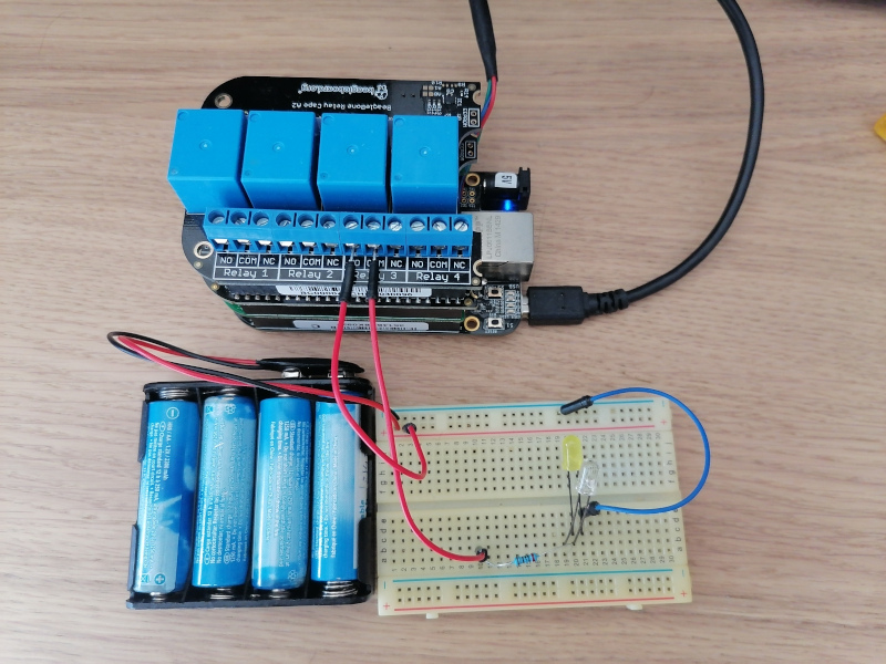
You are ready to connect a real circuit now. When the relay is inactive, the COM (Common) and NO (Normally Open) ports should be disconnected, while COM and NC (Normally Connected) should be connected. When you write 1 to the GPIO, the relay should then connect COM and NO:
The high voltage and low voltage parts of a relay are supposed to be separate and insulated, but in case their was a defect on my cape, I made my tests with a simple low-voltage circuit. However, relays are meant to be used for controlling normal AC voltages (110V / 230V).
Initial state – Relay off
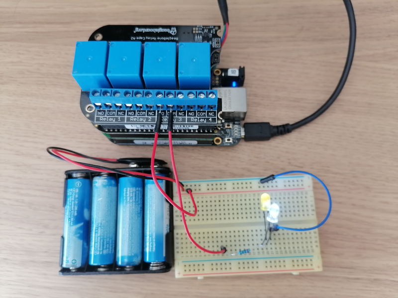
Now, turn on Relay 3 by setting a non zero brightness on the corresponding LED:
echo 1 > /sys/class/leds/relay-jp3/brightness
Relay on, after echo 1 > /sys/class/leds/relay-jp3/brightness
You can turn the relay back off as follows:
echo 0 > /sys/class/leds/relay-jp3/brightness
Don’t hesitate to use this cape in your home automation projects!
What to remember
Device Tree Overlays are Device Tree fragments used to customize the Device Tree of a given board, typically to describe components added externally, including entire expansion boards, or tweak pin multiplexing. That’s the mechanism used by BeagleBoard.org’s kernel developers to support the numerous expansion boards (also known as capes) compatible with their boards. All you have to do is load the main Device Tree Binary for a board (DTB), and then load and apply Device Tree Overlay Binaries (DTBO).
Bootlin thanks BeagleBoard.org for funding the creation of this blog post. Note that more posts are coming in the next weeks, one about the BeagleBone Cape Interface Specification and one about the extension board manager we added to U-Boot.