Linux 5.9 released: Bootlin contributions

Linux 5.9 was released last Sunday. See our usual resources for a good coverage of the highlights of this new release: KernelNewbies page, LWN.net article on the first part of the merge window, LWN.net article on the second part of the merge window.

On our side, we contributed a total of 69 commits to Linux 5.9, which unusually low and makes Bootlin the 31st contributing company by number of commits according to Linux Kernel Patch Statistic. The highlights of our contributions are:

  • Miquèl Raynal reworked part of the rawnand subsystem to allow drivers for non-ONFI compliant NANDs to select a more efficient data interface.
  • On the support of Atmel/Microchip platforms
    • Alexandre Belloni added proper support for the sama5d2 in the TCB (timer counter block) clocksource driver. While doing so, he upstreamd most of the remaining PREEMPT-RT patches for this driver.
    • Kamel Bouhara submitted a new driver for the TCB, this time in the counter subsystem, allowing to count external events, see our post on the topic
  • Antoine Ténart worked on PTP/IEEE 1588 support for the Microchip/Microsemi Ethernet PHYs. This required a change in the core to support a quad PHY properly. The series also included previous work from Quentin Schulz.
  • Paul Kocialkowski added support for the Rockchip PX30 SoC in the V4L2 M2M RGA driver.
  • Maxime Chretien, one of our trainee this year sent a fix for qconf.

Also, several Bootlin engineers are maintainers of various areas of the Linux kernel:

  • Miquèl Raynal, as the NAND maintainer and MTD co-maintainer, reviewed and merged 57 patches from other contributors
  • Alexandre Belloni, as the RTC maintainer and Microchip platform support co-maintainer, reviewed and merged 54 patches from other contributors
  • Grégory Clement, as the Marvell EBU platform support co-maintainer, reviewed and merged 13 patches from other contributors

Here is the complete list of our contributions:

Configuring ALSA controls from an application

ALSA logo
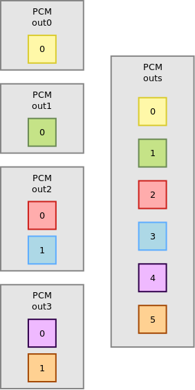
A common task when handling audio on Linux is the need to modify the configuration of the sound card, for example, adjusting the output volume or selecting the capture channels. On an embedded system, it can be enough to simply set the controls once using
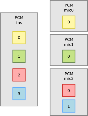
 alsamixer or amixer and then save the configuration with alsactl store. This saves the driver state to the configuration file which, by default, is /var/lib/alsa/asound.state. Once done, this file can be included in the build system and shipped with the root filesystem. Usual distributions already include a script that will invoke alsactl at boot time to restore the settings. If it is not the case, then it is simply a matter of calling alsactl restore.

However, defining a static configuration may not be enough. For example, some codecs have advanced routing features allowing to route the audio channels to different outputs and the application may want to decide at runtime where the audio is going.

Instead of invoking amixer using system(3), even if it is not straightforward, it is possible to directly use the alsa-lib API to set controls.

Let’s start with some required includes:

#include <stdio.h>
#include <alsa/asoundlib.h>

alsa/asoundlib.h is the header that is of interest here as it is where the ALSA API lies. Then we define an id lookup function, which is actually the tricky part. Each control has a unique identifier and to be able to manipulate controls, it is necessary to find this unique identifier. In our sample application, we will be using the control name to do the lookup.

int lookup_id(snd_ctl_elem_id_t *id, snd_ctl_t *handle)
{
	int err;
	snd_ctl_elem_info_t *info;
	snd_ctl_elem_info_alloca(&info);

	snd_ctl_elem_info_set_id(info, id);
	if ((err = snd_ctl_elem_info(handle, info)) < 0) {
		fprintf(stderr, "Cannot find the given element from card\n");
		return err;
	}
	snd_ctl_elem_info_get_id(info, id);

	return 0;
}

This function allocates a snd_ctl_elem_info_t, sets its current id to the one passed as the first argument. At this point, the id only includes the control interface type and its name but not its unique id. The snd_ctl_elem_info() function looks up for the element on the sound card whose handle has been passed as the second argument. Then snd_ctl_elem_info_get_id() updates the id with the now completely filled id.

Then the controls can be modified as follows:

int main(int argc, char *argv[])
{
	int err;
	snd_ctl_t *handle;
	snd_ctl_elem_id_t *id;
	snd_ctl_elem_value_t *value;
	snd_ctl_elem_id_alloca(&id);
	snd_ctl_elem_value_alloca(&value);

This declares and allocates the necessary variables. Allocations are done using alloca so it is not necessary to free them as long as the function exits at some point.

	if ((err = snd_ctl_open(&handle, "hw:0", 0)) < 0) {
		fprintf(stderr, "Card open error: %s\n", snd_strerror(err));
		return err;
	}

Get a handle on the sound card, in this case, hw:0 which is the first sound card in the system.

	snd_ctl_elem_id_set_interface(id, SND_CTL_ELEM_IFACE_MIXER);
	snd_ctl_elem_id_set_name(id, "Headphone Playback Volume");
	if (err = lookup_id(id, handle))
		return err;

This sets the interface type and name of the control we want to modify and then call the lookup function.

	snd_ctl_elem_value_set_id(value, id);
	snd_ctl_elem_value_set_integer(value, 0, 55);
	snd_ctl_elem_value_set_integer(value, 1, 77);

	if ((err = snd_ctl_elem_write(handle, value)) < 0) {
		fprintf(stderr, "Control element write error: %s\n",
			snd_strerror(err));
		return err;
	}

Now, this changes the value of the control. snd_ctl_elem_value_set_id() sets the id of the control to be changed then snd_ctl_elem_value_set_integer() sets the actual value. There are multiple calls because this control has multiple members (in this case, left and right channels). Finally, snd_ctl_elem_write() commits the value.

Note that snd_ctl_elem_value_set_integer() is called directly because we know this control is an integer but it is actually possible to query what kind of value should be used using snd_ctl_elem_info_get_type() on the snd_ctl_elem_info_t. The scale of the integer is also device specific and can be retrieved with the snd_ctl_elem_info_get_min(), snd_ctl_elem_info_get_max() and snd_ctl_elem_info_get_step() helpers.

	snd_ctl_elem_id_clear(id);
	snd_ctl_elem_id_set_interface(id, SND_CTL_ELEM_IFACE_MIXER);
	snd_ctl_elem_id_set_name(id, "Headphone Playback Switch");
	if (err = lookup_id(id, handle))
		return err;

	snd_ctl_elem_value_clear(value);
	snd_ctl_elem_value_set_id(value, id);
	snd_ctl_elem_value_set_boolean(value, 1, 1);

	if ((err = snd_ctl_elem_write(handle, value)) < 0) {
		fprintf(stderr, "Control element write error: %s\n",
			snd_strerror(err));
		return err;
	}

This unmutes the right channel of Headphone playback, this time it is a boolean. The other common kind of element is SND_CTL_ELEM_TYPE_ENUMERATED for enumerated contents. This is used for channel muxing or selecting de-emphasis values for example. snd_ctl_elem_value_set_enumerated() has to be used to set the selected item.

	return 0;
}

This concludes this simple example and should be enough to get you started writing smarter applications that don't rely on external program to configure the sound card controls.

Audio multi-channel routing and mixing using alsalib

ALSA logoRecently, one of our customers designing an embedded Linux system with specific audio needs had a use case where they had a sound card with more than one audio channel, and they needed to separate individual channels so that they can be used by different applications. This is a fairly common use case, we would like to share in this blog post how we achieved this, for both input and output audio channels.

The most common use case would be separating a 4 or 8-channel sound card in multiple stereo PCM devices. For this, alsa-lib, the userspace API interface to the ALSA drivers, provides PCM plugins. Those plugins are configured through configuration files that are usually known to be /etc/asound.conf or $(HOME)/.asoundrc. However, through the configuration of /usr/share/alsa/alsa.conf, it is also possible, and in fact recommended to use a card-specific configuration, named /usr/share/alsa/cards/<card_name>.conf.

The syntax of this configuration is documented in the alsa-lib configuration documentation, and the most interesting part of the documentation for our purpose is the pcm plugin documentation.

Audio inputs

For example, let’s say we have a 4-channel input sound card, which we want to split in 2 mono inputs and one stereo input, as follows:

Audio input example

In the ALSA configuration file, we start by defining the input pcm:

pcm_slave.ins {
	pcm "hw:0,1"
	rate 44100
	channels 4
}

pcm "hw:0,1" refers to the the second subdevice of the first sound card present in the system. In our case, this is the capture device. rate and channels specify the parameters of the stream we want to set up for the device. It is not strictly necessary but this allows to enable automatic sample rate or size conversion if this is desired.

Then we can split the inputs:

pcm.mic0 {
	type dsnoop
	ipc_key 12342
	slave ins
	bindings.0 0
}

pcm.mic1 {
	type plug
	slave.pcm {
		type dsnoop
		ipc_key 12342
		slave ins
		bindings.0 1
	}
}

pcm.mic2 {
	type dsnoop
	ipc_key 12342
	slave ins
	bindings.0 2
	bindings.1 3
}

mic0 is of type dsnoop, this is the plugin splitting capture PCMs. The ipc_key is an integer that has to be unique: it is used internally to share buffers. slave indicates the underlying PCM that will be split, it refers to the PCM device we have defined before, with the name ins. Finally, bindings is an array mapping the PCM channels to its slave channels. This is why mic0 and mic1, which are mono inputs, both only use bindings.0, while mic2 being stereo has both bindings.0 and bindings.1. Overall, mic0 will have channel 0 of our input PCM, mic1 will have channel 1 of our input PCM, and mic2 will have channels 2 and 3 of our input PCM.

The final interesting thing in this example is the difference between mic0 and mic1. While mic0 and mic2 will not do any conversion on their stream and pass it as is to the slave pcm, mic1 is using the automatic conversion plugin, plug. So whatever type of stream will be requested by the application, what is provided by the sound card will be converted to the correct format and rate. This conversion is done in software and so runs on the CPU, which is usually something that should be avoided on an embedded system.

Also, note that the channel splitting happens at the dsnoop level. Doing it at an upper level would mean that the 4 channels would be copied before being split. For example the following configuration would be a mistake:

pcm.dsnoop {
    type dsnoop
    ipc_key 512
    slave {
        pcm "hw:0,0"
        rate 44100
    }
}

pcm.mic0 {
    type plug
    slave dsnoop
    ttable.0.0 1
}

pcm.mic1 {
    type plug
    slave dsnoop
    ttable.0.1 1
}

Audio outputs

For this example, let’s say we have a 6-channel output that we want to split in 2 mono outputs and 2 stereo outputs:

Audio output example

As before, let’s define the slave PCM for convenience:

pcm_slave.outs {
	pcm "hw:0,0"
	rate 44100
	channels 6
}

Now, for the split:

pcm.out0 {
	type dshare
	ipc_key 4242
	slave outs
	bindings.0 0
}

pcm.out1 {
	type plug {
	slave.pcm {
		type dshare
		ipc_key 4242
		slave outs
		bindings.0 1
	}
}

pcm.out2 {
	type dshare
	ipc_key 4242
	slave outs
	bindings.0 2
	bindings.0 3
}

pcm.out3 {
	type dmix
	ipc_key 4242
	slave outs
	bindings.0 4
	bindings.0 5
}

out0 is of type dshare. While usually dmix is presented as the reverse of dsnoop, dshare is more efficient as it simply gives exclusive access to channels instead of potentially software mixing multiple streams into one. Again, the difference can be significant in terms of CPU utilization in the embedded space. Then, nothing new compared to the audio input example before:

  • out1 is allowing sample format and rate conversion
  • out2 is stereo
  • out3 is stereo and allows multiple concurrent users that will be mixed together as it is of type dmix

A common mistake here would be to use the route plugin on top of dmix to split the streams: this would first transform the mono or stereo stream in 6-channel streams and then mix them all together. All these operations would be costly in CPU utilization while dshare is basically free.

Duplicating streams

Another common use case is trying to copy the same PCM stream to multiple outputs. For example, we have a mono stream, which we want to duplicate into a stereo stream, and then feed this stereo stream to specific channels of a hardware device. This can be achieved using the following configuration snippet:

pcm.out4 {
	type route;
	slave.pcm {
	type dshare
		ipc_key 4242
		slave outs
		bindings.0 0
		bindings.1 5
	}
	ttable.0.0 1;
	ttable.0.1 1;
}

The route plugin allows to duplicate the mono stream into a stereo stream, using the ttable property. Then, the dshare plugin is used to get the first channel of this stereo stream and send it to the hardware first channel (bindings.0 0), while sending the second channel of the stereo stream to the hardware sixth channel (bindings.1 5).

Conclusion

When properly used, the dsnoop, dshare and dmix plugins can be very efficient. In our case, simply rewriting the alsalib configuration on an i.MX6 based system with a 16-channel sound card dropped the CPU utilization from 97% to 1-3%, leaving plenty of CPU time to run further audio processing and other applications.

Feedback from the SiFive Tech Symposium in Grenoble

SiFive LogoSiFive is a semi-conductor company that produces chips based on the RISC-V architecture. On May 15th, they organized a Technical Symposium in Grenoble on May 15th and we took the opportunity to attend, as the agenda looked interesting.

It was especially nice having Krste Asanovic present many of the topics, wearing different hats (RISC-V Foundation Chairman of the Board and SiFive Co-Founder and Chief Architect). The RISC-V architecture and its history and use cases were presented. One of the main benefit of having a brand new ISA (instruction set architecture), Asanovic said, is that it doesn’t have to handle legacy instructions and compatibility. Moreover, RISC-V is a frozen ISA, the base instructions are frozen and optional extensions which have been approved are also frozen. Finally, the ISA is open and anybody can implement a CPU core. During the presentation, the RISC-V ISA was (obviously) favorably compared to competing ISAs, mainly ARM.

Another interesting topic was the presentation of SiFive’s business model. They want anyone, including small companies to be able to design an SoC fitting their particular product, instead of having to choose from a set of more general purpose SoC. This can be done by using an existing SiFive RISC-V core or by customizing one. SiFive then offers a library of IPs that can be added on the SoC and third party IPs are available through their Designshare program. They handle NDA, contract and licensing and will collect non recurring engineering costs and royalties once the SoC is mass produced but not during the prototyping phase. They first provide virtualized chips and then sample chips. For the core, they also provide RTL that can run on FPGAs. For mass production, SiFive partnered with TSMC and their customers can benefit from their process (down to 7nm).

The most relevant topic for us was the software ecosystem. There is a very nice will to get code upstream and this is the case for GCC, binutils, newlib, gdb, glibc, qemu. Clang/LLVM is coming up. Regarding the Linux kernel port, it still requires some work as the core architecture support is there but no devices drivers or device tree support yet. There is however a fully working vendor tree. FreeBSD seems to be in the same state.

Most of the remaining time was focused on the design and customization tool available here.
SiFive Chip Designer

SiFive also Sponsored Linus Sebastian (from Linus Tech Tips) for a video:

To conclude, it was an very interesting day. At Bootlin, we are delighted to see architecture designers and silicon vendors actively pushing software support upstream and we are looking forward to work on RISC-V platforms.

Using the Cortex-M4 MCU on the i.MX6 SoloX from Linux

Introduction

The NXP i.MX6 SoloX System on Chip has two different CPU cores (i.e. Assymetric Multi Processing), a Cortex-A9 and a Cortex-M4. The Cortex-M4 MCU allows running an hard real-time OS while still having access to all the SoC peripherals.

This post is about running an application on the Cortex-M4, loading it from the Linux userspace. The i.MX 6SoloX SABRE Development Board is used for this demonstration.
It doesn’t describe in details how to build the BSP but the meta-freescale Yocto Project layer has been used. The kernel is a vendor kernel derivative, linux-fslc.

Building the cortex M4 binary

We will be running FreeRTOS on the Cortex-M4. The BSP is available from the NXP website (it may require registration).

Uncompress it:

$ tar xf FreeRTOS_BSP_1.0.1_iMX6SX.tar.gz

A baremetal toolchain is needed to compile for Cortex-M4. One is available from ARM.

Download it and uncompress it:

$ wget https://armkeil.blob.core.windows.net/developer/Files/downloads/gnu-rm/7-2018q2/gcc-arm-none-eabi-7-2018-q2-update-linux.tar.bz2
$ tar xf gcc-arm-none-eabi-7-2018-q2-update-linux.tar.bz2

The provided examples will have the Cortex-M4 output debug on one of the SoC UART. Unfortunately, the hardware setup code will forcefully try to use the 24MHz oscillator as the clock parent for the UART and because Linux is using a 80MHz clock, running the examples as-is would result in a non functioning Linux console.

The following patch solves this issue:

diff -burp a/examples/imx6sx_sdb_m4/board.c b/examples/imx6sx_sdb_m4/board.c
--- a/examples/imx6sx_sdb_m4/board.c
+++ b/examples/imx6sx_sdb_m4/board.c
@@ -69,10 +69,12 @@ void dbg_uart_init(void)
     /* Set debug uart for M4 core domain access only */
     RDC_SetPdapAccess(RDC, BOARD_DEBUG_UART_RDC_PDAP, 3 << (BOARD_DOMAIN_ID * 2), false, false);
 
+#if 0
     /* Select board debug clock derived from OSC clock(24M) */
     CCM_SetRootMux(CCM, ccmRootUartClkSel, ccmRootmuxUartClkOsc24m);
     /* Set relevant divider = 1. */
     CCM_SetRootDivider(CCM, ccmRootUartClkPodf, 0);
+#endif
     /* Enable debug uart clock */
     CCM_ControlGate(CCM, ccmCcgrGateUartClk, ccmClockNeededAll);
     CCM_ControlGate(CCM, ccmCcgrGateUartSerialClk, ccmClockNeededAll);
@@ -80,7 +82,7 @@ void dbg_uart_init(void)
     /* Configure the pin IOMUX */
     configure_uart_pins(BOARD_DEBUG_UART_BASEADDR);
 
-    DbgConsole_Init(BOARD_DEBUG_UART_BASEADDR, 24000000, 115200);
+    DbgConsole_Init(BOARD_DEBUG_UART_BASEADDR, 80000000, 115200);
 }
 
 /*FUNCTION*---------------------------------------------------------------------

After applying that, let's build some examples.

$ cd FreeRTOS_BSP_1.0.1_iMX6SX/examples/imx6sx_sdb_m4/demo_apps/hello_world/armgcc
$ ARMGCC_DIR=~/gcc-arm-none-eabi-7-2018-q2-update ./build_release.sh
...
[100%] Linking C executable release/hello_world.elf
[100%] Built target hello_world
$ cd ../../rpmsg/pingpong_freertos/armgcc/
$ ARMGCC_DIR=~/gcc-arm-none-eabi-7-2018-q2-update ./build_release.sh
...
[100%] Linking C executable release/rpmsg_pingpong_freertos_example.elf
[100%] Built target rpmsg_pingpong_freertos_example
$ cd ../../str_echo_freertos/armgcc/i
$ ARMGCC_DIR=~/gcc-arm-none-eabi-7-2018-q2-update ./build_release.sh
...
[100%] Linking C executable release/rpmsg_str_echo_freertos_example.elf
[100%] Built target rpmsg_str_echo_freertos_example

The generated binaries are in FreeRTOS_BSP_1.0.1_iMX6SX/examples/imx6sx_sdb_m4/demo_apps/:

  • rpmsg/pingpong_freertos/armgcc/release/rpmsg_pingpong_freertos_example.bin
  • rpmsg/str_echo_freertos/armgcc/release/rpmsg_str_echo_freertos_example.bin
  • hello_world/armgcc/release/hello_world.bin

Copy them to your root filessystem.

Loading the M4 binary

NXP provides a userspace application allowing to load the binary on the Cortex-M4 from Linux: imx-m4fwloader.

Unfortunately, this doesn't work out of the box because the code in the vendor kernel is expecting the Cortex-M4 to be started by u-boot to initialize communication channels between the Cortex-A9 and the Cortex-M4, specifically the shared memory area containing the clocks status and the Cortex-M4 clock.

The following hack ensures the initialization is done and the Cortex-M4 clock is left enabled after boot:

diff --git a/arch/arm/mach-imx/src.c b/arch/arm/mach-imx/src.c
index c53b6da411b9..9859751b5109 100644
--- a/arch/arm/mach-imx/src.c
+++ b/arch/arm/mach-imx/src.c
@@ -194,6 +194,7 @@ void __init imx_src_init(void)
 		m4_is_enabled = true;
 	else
 		m4_is_enabled = false;
+	m4_is_enabled = true;
 
 	val &= ~(1 << BP_SRC_SCR_WARM_RESET_ENABLE);
 	writel_relaxed(val, src_base + SRC_SCR);

Don't forget to use the -m4 version of the device tree (i.e imx6sx-sdb-m4.dtb), else the kernel will crash with the following dump:

Unable to handle kernel NULL pointer dereference at virtual address 00000018
pgd = 80004000
[00000018] *pgd=00000000
Internal error: Oops: 805 [#1] PREEMPT SMP ARM
Modules linked in:
CPU: 0 PID: 1 Comm: swapper/0 Not tainted 4.9.67-fslc-02224-g953c6e30c970-dirty #6
Hardware name: Freescale i.MX6 SoloX (Device Tree)
task: a80bc000 task.stack: a8120000
PC is at imx_amp_power_init+0x98/0xdc
LR is at 0xa8003b00
pc : [<810462ec>]    lr : []    psr: 80000013
sp : a8121ec0  ip : 812241cc  fp : a8121ed4
r10: 8109083c  r9 : 00000008  r8 : 00000000
r7 : 81090838  r6 : 811c9000  r5 : ffffe000  r4 : 81223d78
r3 : 00000001  r2 : 0000001c  r1 : 00000001  r0 : 00000000
Flags: Nzcv  IRQs on  FIQs on  Mode SVC_32  ISA ARM  Segment none
Control: 10c53c7d  Table: 8000404a  DAC: 00000051
Process swapper/0 (pid: 1, stack limit = 0xa8120210)
Stack: (0xa8121ec0 to 0xa8122000)
1ec0: 81046254 ffffe000 a8121f4c a8121ed8 80101c7c 81046260 81000638 8045f190
1ee0: abfff9ad 80b35338 a8121f00 a8121ef8 801522e0 81000628 a8121f34 80d4aefc
1f00: 80d4a754 80d57578 00000007 00000007 00000000 80e59e78 80d96100 00000000
1f20: 81090818 80e59e78 811c9000 80e59e78 810c3c70 811c9000 81090838 811c9000
1f40: a8121f94 a8121f50 81000ea0 80101c34 00000007 00000007 00000000 8100061c
1f60: 8100061c 00000130 dc911044 00000000 80ab005c 00000000 00000000 00000000
1f80: 00000000 00000000 a8121fac a8121f98 80ab0074 81000d40 00000000 80ab005c
1fa0: 00000000 a8121fb0 80108378 80ab0068 00000000 00000000 00000000 00000000
1fc0: 00000000 00000000 00000000 00000000 00000000 00000000 00000000 00000000
1fe0: 00000000 00000000 00000000 00000000 00000013 00000000 6ff3be9f f9fde415
[<810462ec>] (imx_amp_power_init) from [<80101c7c>] (do_one_initcall+0x54/0x17c)
[<80101c7c>] (do_one_initcall) from [<81000ea0>] (kernel_init_freeable+0x16c/0x200)
[<81000ea0>] (kernel_init_freeable) from [<80ab0074>] (kernel_init+0x18/0x120)
[<80ab0074>] (kernel_init) from [<80108378>] (ret_from_fork+0x14/0x3c)
Code: 0a000005 e79ce103 e2833001 e794e10e (e5421004) 
---[ end trace 0b1d1e3108025c69 ]---
Kernel panic - not syncing: Attempted to kill init! exitcode=0x0000000b

Running the examples

With all of that in place, we can now load the first example, a simple hello world on the Cortex-M4:

On the Cortex-A9:

# ./m4fwloader hello_world.bin 0x7f8000

Output from the Cortex-M4:

Hello World!

0x7f8000 is the address of the TCM. That is the memory from where the Cortex-M4 is running the code. The OCRAM or the regular DDR can also be used.

The first RPMSG example allows sending strings from the Cortex-A9 to the Cortex-M4 using a tty character device:

On the Cortex-A9:

# ./m4fwloader rpmsg_str_echo_freertos_example.bin 0x7f8000
virtio_rpmsg_bus virtio0: creating channel rpmsg-openamp-demo-channel addr 0x0
# insmod ./imx_rpmsg_tty.ko
imx_rpmsg_tty virtio0.rpmsg-openamp-demo-channel.-1.0: new channel: 0x400 -> 0x0!
Install rpmsg tty driver!
# echo test > /dev/ttyRPMSG
#

Output from the Cortex-M4:

RPMSG String Echo FreeRTOS RTOS API Demo...
RPMSG Init as Remote
Name service handshake is done, M4 has setup a rpmsg channel [0 ---> 1024]
Get Message From Master Side : "test" [len : 4]
Get New Line From Master Side

The other RPMSG example is a ping pong between the Cortex-A9 and the
Cortex-M4:

On the Cortex-A9:

# ./m4fwloader rpmsg_pingpong_freertos_example.bin 0x7f8000
virtio_rpmsg_bus virtio0: creating channel rpmsg-openamp-demo-channel addr 0x0
# insmod ./imx_rpmsg_pingpong.ko
imx_rpmsg_pingpong virtio0.rpmsg-openamp-demo-channel.-1.0: new channel: 0x400 -> 0x0!
# get 1 (src: 0x0)
get 3 (src: 0x0)
get 5 (src: 0x0)
get 7 (src: 0x0)
get 9 (src: 0x0)
get 11 (src: 0x0)
get 13 (src: 0x0)
get 15 (src: 0x0)
get 17 (src: 0x0)
get 19 (src: 0x0)
get 21 (src: 0x0)
get 23 (src: 0x0)
get 25 (src: 0x0)
get 27 (src: 0x0)
get 29 (src: 0x0)
get 31 (src: 0x0)
get 33 (src: 0x0)
get 35 (src: 0x0)
get 37 (src: 0x0)
get 39 (src: 0x0)

Output from the Cortex-M4:

RPMSG PingPong FreeRTOS RTOS API Demo...
RPMSG Init as Remote
Name service handshake is done, M4 has setup a rpmsg channel [0 ---> 1024]
Get Data From Master Side : 0
Get Data From Master Side : 2
Get Data From Master Side : 4
Get Data From Master Side : 6
Get Data From Master Side : 8
Get Data From Master Side : 10
Get Data From Master Side : 12
Get Data From Master Side : 14
Get Data From Master Side : 16
Get Data From Master Side : 18
Get Data From Master Side : 20
Get Data From Master Side : 22
Get Data From Master Side : 24
Get Data From Master Side : 26
Get Data From Master Side : 28
Get Data From Master Side : 30
Get Data From Master Side : 32
Get Data From Master Side : 34
Get Data From Master Side : 36
Get Data From Master Side : 38
Get Data From Master Side : 40

Conclusion

While loading and reloading a Cortex-M4 firmware from Linux doesn't work out of the box, it is possible to make that work without too many modifications.

We usually prefer working with an upstream kernel. Upstream, there is a remoteproc driver, drivers/remoteproc/imx_rproc.c which is a much cleaner and generic way of loading a firmware on the Cortex-M4.

Upstream Linux support for Microsemi Ethernet Switch

VSC7513 Block Diagram
Microsemi VSC7513 Block Diagram
Starting last year, we have been working on the Microsemi VSC7513 and VSC7514 MIPS processors.

They have a 500 MHz MIPS 24KEc CPU and the usual DDR, UART, I2C and SPI controllers. But more interestingly, they also have an 8 or 10-port Gigabit Ethernet switch allowing to offload common network bridging operations to the hardware. As is usual for that kind of products, the vendor-provided SDK (called WebStaX) used to configure the switch is running in userspace and uses a custom in-kernel UIO driver to talk to the hardware.

However, this has now changed as we submitted support for the platform and the switch to the upstream Linux kernel:

The whole driver based on the switchdev Linux kernel subsystem, is about 5700 lines long.

Microsemi VSC7514EV

Thanks to this work, it is now possible to use standard Linux user-space tools to configure the switch. For example, the following will bridge the switch port and offload to the hardware:

ip link add name br0 type bridge
ip link set dev sw0p0 master br0
ip link set dev sw0p1 master br0

To achieve hardware offloading, the driver needs to:

  • configure port forwarding i.e. to what port the frames coming form a particular port should be forwarded;
  • handle the MAC table: this table is the one used to know on which port which machine is connected. Also, the broadcast and multicast MAC have to be installed;
  • handle STP port state: whether the port is allowed to forward frames or learn new MAC addresses;

VLANs are configured using ip and bridge:

ip link set dev br0 type bridge vlan_filtering 1
bridge vlan add dev sw0p0 vid 1 pvid untagged
bridge vlan add dev sw0p1 vid 1
bridge vlan add dev sw0p0 vid 30
bridge vlan add dev sw0p1 vid 30

Here, the driver configures the VIDs on each port and what to do about them (tag, untag, forward).

Configuring link aggregation is also done with ip:

ip link add name aggr0 type bond
ip link set dev eth_yellow master aggr0
ip link set dev eth_blue master aggr0

The driver has to configure the aggregated ports and the balancing mode. It also has to ensure the switch will forward the control frame (LACPDUs) to the CPU so Linux can know the state of the links.

IGMP snooping is a simple feature where the switch is able to push new multicast addresses to the CPU so Linux can install the MACs in the table and avoid having to forward the multicast frames on all the switch ports. In our case, it is simply enabled using a single register when multicasting is enabled on the bridge.

The switch supports more features to be worked on: PTP timestamping, QoS and packet filtering to name a few. We have already implemented PTP support, and we will be submitting upstream this additional feature in the near future.

To learn more about the inner workings of switchdev, you can refer to Alexandre Belloni’s ELC talk:


If you’re interested about upstream Linux kernel support for other Ethernet switches, do not hesitate to contact us!

Eight channels audio on i.MX7 with PCM3168

Toradex Colibri i.MX7Bootlin engineer Alexandre Belloni recently worked on a custom carrier board for a Colibri iMX7 system-on-module from Toradex. This system-on-module obviously uses the i.MX7 ARM processor from Freescale/NXP.

While the module includes an SGTL5000 codec, one of the requirements for that project was to handle up to eight audio channels. The SGTL5000 uses I²S and handles only two channels.

I2S

I2S timing diagram from the SGTL5000 datasheet

Thankfully, the i.MX7 has multiple audio interfaces and one is fully available on the SODIMM connector of the Colibri iMX7. A TI PCM3168 was chosen for the carrier board and is connected to the second Synchronous Audio Interface (SAI2) of the i.MX7. This codec can handle up to 8 output channels and 6 input channels. It can take multiple formats as its input but TDM takes the smaller number of signals (4 signals: bit clock, word clock, data input and data output).


TDM timing diagram from the PCM3168 datasheet

The current Linux long term support version is 4.9 and was chosen for this project. It has support for both the i.MX7 SAI (sound/soc/fsl/fsl_sai.c) and the PCM3168 (sound/soc/codecs/pcm3168a.c). That’s two of the three components that are needed, the last one being the driver linking both by describing the topology of the “sound card”. In order to keep the custom code to the minimum, there is an existing generic driver called simple-card (sound/soc/generic/simple-card.c). It is always worth trying to use it unless something really specific prevents that. Using it was as simple as writing the following DT node:

        board_sound {
                compatible = "simple-audio-card";
                simple-audio-card,name = "imx7-pcm3168";
                simple-audio-card,widgets =
                        "Speaker", "Channel1out",
                        "Speaker", "Channel2out",
                        "Speaker", "Channel3out",
                        "Speaker", "Channel4out",
                        "Microphone", "Channel1in",
                        "Microphone", "Channel2in",
                        "Microphone", "Channel3in",
                        "Microphone", "Channel4in";
                simple-audio-card,routing =
                        "Channel1out", "AOUT1L",
                        "Channel2out", "AOUT1R",
                        "Channel3out", "AOUT2L",
                        "Channel4out", "AOUT2R",
                        "Channel1in", "AIN1L",
                        "Channel2in", "AIN1R",
                        "Channel3in", "AIN2L",
                        "Channel4in", "AIN2R";

                simple-audio-card,dai-link@0 {
                        format = "left_j";
                        bitclock-master = <&pcm3168_dac>;
                        frame-master = <&pcm3168_dac>;
                        frame-inversion;

                        cpu {
                                sound-dai = <&sai2>;
                                dai-tdm-slot-num = <8>;
                                dai-tdm-slot-width = <32>;
                        };

                        pcm3168_dac: codec {
                                sound-dai = <&pcm3168 0>;
                                clocks = <&codec_osc>;
                        };
                };

                simple-audio-card,dai-link@2 {
                        format = "left_j";
                        bitclock-master = <&pcm3168_adc>;
                        frame-master = <&pcm3168_adc>;

                        cpu {
                                sound-dai = <&sai2>;
                                dai-tdm-slot-num = <8>;
                                dai-tdm-slot-width = <32>;
                        };

                        pcm3168_adc: codec {
                                sound-dai = <&pcm3168 1>;
                                clocks = <&codec_osc>;
                        };
                };
        };

There are multiple things of interest:

  • Only 4 input channels and 4 output channels are routed because the carrier board only had that wired.
  • There are two DAI links because the pcm3168 driver exposes inputs and outputs separately
  • As per the PCM3168 datasheet:
    • left justified mode is used
    • dai-tdm-slot-num is set to 8 even though only 4 are actually used
    • dai-tdm-slot-width is set to 32 because the codec takes 24-bit samples but requires 32 clocks per sample (this is solved later in userspace)
    • The codec is master which is usually best regarding clock accuracy, especially since the various SoMs on the market almost never expose the audio clock on the carrier board interface. Here, a crystal was used to clock the PCM3168.

The PCM3168 codec is added under the ecspi3 node as that is where it is connected:

&ecspi3 {
        pcm3168: codec@0 {
                compatible = "ti,pcm3168a";
                reg = <0>;
                spi-max-frequency = <1000000>;
                clocks = <&codec_osc>;
                clock-names = "scki";
                #sound-dai-cells = <1>;
                VDD1-supply = <&reg_module_3v3>;
                VDD2-supply = <&reg_module_3v3>;
                VCCAD1-supply = <&reg_board_5v0>;
                VCCAD2-supply = <&reg_board_5v0>;
                VCCDA1-supply = <&reg_board_5v0>;
                VCCDA2-supply = <&reg_board_5v0>;
        };
};

#sound-dai-cells is what allows to select between the input and output interfaces.

On top of that, multiple issues had to be fixed:

Finally, an ALSA configuration file (/usr/share/alsa/cards/imx7-pcm3168.conf) was written to ensure samples sent to the card are in the proper format, S32_LE. 24-bit samples will simply have zeroes in the least significant byte. For 32-bit samples, the codec will properly ignore the least significant byte.
Also this describes that the first subdevice is the playback (output) device and the second subdevice is the capture (input) device.

imx7-pcm3168.pcm.default {
	@args [ CARD ]
	@args.CARD {
		type string
	}
	type asym
	playback.pcm {
		type plug
		slave {
			pcm {
				type hw
				card $CARD
				device 0
			}
			format S32_LE
			rate 48000
			channels 4
		}
	}
	capture.pcm {
		type plug
		slave {
			pcm {
				type hw
				card $CARD
				device 1
			}
			format S32_LE
			rate 48000
			channels 4
		}
	}
}

On top of that, the dmix and dsnoop ALSA plugins can be used to separate channels.

To conclude, this shows that it is possible to easily leverage existing code to integrate an audio codec in a design by simply writing a device tree snippet and maybe an ALSA configuration file if necessary.

Linux 4.8 released, Bootlin contributions

Adelie PenguinLinux 4.8 has been released on Sunday by Linus Torvalds, with numerous new features and improvements that have been described in details on LWN: part 1, part 2 and part 3. KernelNewbies also has an updated page on the 4.8 release. We contributed a total of 153 patches to this release. LWN also published some statistics about this development cycle.

Our most significant contributions:

  • Boris Brezillon improved the Rockchip PWM driver to avoid glitches basing that work on his previous improvement to the PWM subsystem already merged in the kernel. He also fixed a few issues and shortcomings in the pwm regulator driver. This is finishing his work on the Rockchip based Chromebook platforms where a PWM is used for a regulator.
  • While working on the driver for the sii902x HDMI transceiver, Boris Brezillon did a cleanup of many DRM drivers. Those drivers were open coding the encoder selection. This is now done in the core DRM subsystem.
  • On the support of Atmel platforms
    • Alexandre Belloni cleaned up the existing board device trees, removing unused clock definitions and starting to remove warnings when compiling with the Device Tree Compiler (dtc).
  • On the support of Allwinner platforms
    • Maxime Ripard contributed a brand new infrastructure, named sunxi-ng, to manage the clocks of the Allwinner platforms, fixing shortcomings of the Device Tree representation used by the existing implementation. He moved the support of the Allwinner H3 clocks to this new infrastructure.
    • Maxime also developed a driver for the Allwinner A10 Digital Audio controller, bringing audio support to this platform.
    • Boris Brezillon improved the Allwinner NAND controller driver to support DMA assisted operations, which brings a very nice speed-up to throughput on platforms using NAND flashes as the storage, which is the case of Nextthing’s C.H.I.P.
    • Quentin Schulz added support for the Allwinner R16 EVB (Parrot) board.
  • On the support of Marvell platforms
    • Grégory Clément added multiple clock definitions for the Armada 37xx series of SoCs.
    • He also corrected a few issues with the I/O coherency on some Marvell SoCs
    • Romain Perier worked on the Marvell CESA cryptography driver, bringing significant performance improvements, especially for dmcrypt usage. This driver is used on numerous Marvell platforms: Orion, Kirkwood, Armada 370, XP, 375 and 38x.
    • Thomas Petazzoni submitted a driver for the Aardvark PCI host controller present in the Armada 3700, enabling PCI support for this platform.
    • Thomas also added a driver for the new XOR engine found in the Armada 7K and Armada 8K families

Here are in details, the different contributions we made to this release:

Embedded Linux Projects Using Yocto Project Cookbook

Embedded Linux Projects Using Yocto Project Cookbook Cover

We were kindly provided a copy of Embedded Linux Projects Using Yocto Project Cookbook, written by Alex González. It is available at Packt Publishing, either in an electronic format (DRM free) or printed.

It is written as a cookbook so it is a set of recipes that you can refer to and solve your immediate problems instead of reading it from cover to cover. While, as indicated by the title, the main topic is embedded development using Yocto Project, the book also includes generic embedded Linux tips, like debugging the kernel with ftrace or debugging a device tree from U-Boot.

The chapters cover the following topics:

  • The Build System: an introduction to Yocto Project.
  • The BSP Layer: how to build and customize the bootloader and the Linux kernel, plenty of tips on how to debug kernel related issues.
  • The Software layer: covers adding a package and its configuration, selecting the initialization manager and making a release while complying with the various licenses.
  • Application development: using the SDK, various IDEs (Eclipse, Qt creator), build systems (make, CMake, SCons).
  • Debugging, Tracing and Profiling: great examples and tips for the usage of gdb, strace, perf, systemtap, OProfile, LTTng and blktrace.

The structure of the book makes it is easy to find the answers you are looking for and also explains the underlying concepts of the solution. It is definitively of good value once you start using Yocto Project.

Bootlin is also offering a Yocto Project and OpenEmbedded training course (detailed agenda) to help you start with your projects. If you’re interested, join one of the upcoming public training sessions, or order a session at your location!

Bootlin registered as Yocto Project Participant.

Yocto_Project_Badge_Participant_Web_RGB
Earlier this month, Bootlin applied and was elected Yocto Project Participant by the Yocto Project Advisory Board. This badge is awarded to people and companies actively participating to the Yocto Project and promoting it.

We have mainly contributed to the meta-fsl-arm and meta-fsl-arm-extra layers but we also have some contributions in OpenEmbedded Core and in the meta-ti layer.

Bootlin offers a Yocto Project and OpenEmbedded training course that we can deliver at your location, or that you can attend by joining one of our public sessions. Our engineers are also available to provide consulting and development services around the Yocto Project, to help you use this tool for your embedded Linux projects. Do not hesitate to contact us!