We recently worked on Linux support for a custom hardware platform based on the Texas Instruments AM335x system-on-chip, with a somewhat special networking setup: each of the two ports of the AM335x Ethernet MAC was connected to a Microchip VSC8572 Ethernet PHY, which itself allowed to access an SFP cage. In addition, the I2C buses connected to the SFP cages, which are used at runtime to communicate with the inserted SFP modules, instead of being connected to an I2C controller of the system-on-chip as they usually are, where connected to the I2C controller embedded in the VSC8572 PHYs.
The below diagram depicts the overall hardware layout:
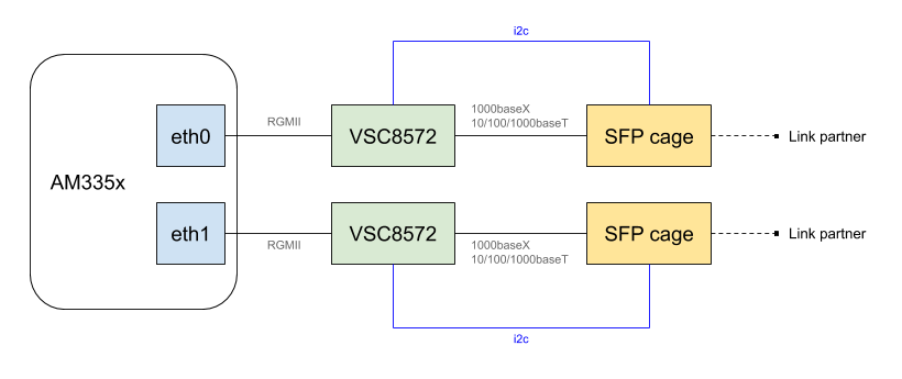
Our goal was to use Linux and to offer runtime dynamic reconfiguration of the networking links based the SFP module plugged in. To achieve this we used, and extended, a combination of Linux kernel internal frameworks such as Phylink or the SFP bus support; and of networking device drivers. In this blog post, we’ll share some background information about these technologies, the challenges we faced and our current status.
Introduction to the SFP interface
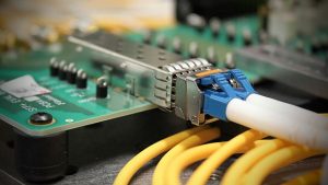 The small form-factor pluggable (SFP) is a hot-pluggable network interface module. Its electrical interface and its form-factor are well specified, which allows industry players to build platforms that can host SFP modules, and be sure that they will be able to use any available SFP module on the market. It is commonly used in the networking industry as it allows connecting various types of transceivers to a fixed interface.
A SFP cage provides in addition to data signals a number of control signals:
- a Tx_Fault pin, for transmitter fault indication
- a Tx_Disable pin, for disabling optical output
- a MOD_Abs pin, to detect the absence of a module
- an Rx_LOS pin, to denote a receiver loss of signal
- a 2-wire data and clock lines, used to communicate with the modules
Modules plugged into SFP cages can be direct attached cables, in which case they do not have any built-in transceiver, or they can include a transceiver (i.e an embedded PHY), which transforms the signal into another format. This means that in our setup, there can be two PHYs between the Ethernet MAC and the physical medium: the Microchip VSC8572 PHY and the PHY embedded into the SFP module that is plugged in.
All SFP modules embed an EEPROM, accessible at a standardized I2C address and with a standardized format, which allows the host system to discover which SFP modules are connected what are their capabilities. In addition, if the SFP modules contains an embedded PHY, it is also accessible through the same I2C bus.
Challenges
We had to overcome a few challenges to get this setup working, using a mainline Linux kernel.
As we discussed earlier, having SFP modules meant the whole MAC-PHY-SFP link has to be reconfigured at runtime, as the PHY in the SFP module is hot-pluggable. To solve this issue a framework called Phylink, was introduced in mid-2017 to represent networking links and allowing their component to share states and to be reconfigured at runtime. For us, this meant we had to first convert the CPSW MAC driver to use this phylink framework. For a detailed explanation of what composes Ethernet links and why Phylink is needed, we gave a talk at the Embedded Linux Conference Europe in 2018. While we were working on this and after we first moved the CPSW MAC driver to use Phylink, this driver was rewritten and a new CPSW MAC driver was sent upstream (CONFIG_TI_CPSW vs CONFIG_TI_CPSW_SWITCHDEV). We are still using the old driver for now, and this is why we did not send our patches upstream as we think it does not make sense to convert a driver which is now deprecated.
A second challenge was to integrate the 2-wire capability of the VSC8572 PHY into the networking PHY and SFP common code, as our SFP modules I2C bus is connected to the PHY and not an I2C controller from the system-on-chip. We decided to expose this PHY 2-wire capability as an SMBus controller, as the functionality offered by the PHY does not make it a fully I2C compliant controller.
Outcome
The challenges described above made the project quite complex overall, but we were able to get SFP modules working, and to dynamically switch modes depending on the capabilities of the one currently plugged-in. We tested with both direct attached cables and a wide variety of SFP modules of different speeds and functionality. At the moment only a few patches were sent upstream, but we’ll contribute more over time.
For an overview of some of the patches we made and used, we pushed a branch on Github (be aware those patches aren’t upstream yet and they will need some further work to be acceptable upstream). Here is the details of the patches:
- net: phy: mscc: add support for RGMII MAC mode” extends the VSC8572 PHY driver to support RGMII interface as a host interface. Indeed, only SGMII and QSGMII were supported so far.
- net: phy: mscc: RGMII skew delay configuration also extends the VSC8572 PHY driver to configure the RGMII skew delays<
- net: phy: mscc: add SFP operations extends the VSC8572 PHY driver to implement the
struct sfp_upstream_ops operations, needed to support SFP modules, and registers them using phy_sfp_probe().
- net: phy: mscc: allow selecting the media mode extends the VSC8572 PHY driver to be able to select the media mode using a Device Tree property. Indeed, until now, the copper media mode was unconditionally selected, why we needed the fiber mode in our use-case.
- net: phy: mscc: support LOS being active low also extends the same driver, to support a LOS pin that is active low, according to a Device Tree property
- net: phy: sfp-bus: set 100baseT modes slightly extends the SFP core to support 100 Mbit/s SFP modules, which we have tested.
- net: phy: sfp: re-probe modules on DEV_UP event is a hack to work-around the lack of status reporting from the CPSW MAC: we re-probe SFP modules when an interface is brought up.
- net: phy: allow to expose and i2c controller extends the PHY driver core to allow a PHY driver to also expose an I2C controller: if a PHY Device Tree node has a
i2c-controller property, then we register a new I2C controller, which is implemented using the new ->i2c_xfer() operation of struct phy_driver.
- net: phy: add an MDIO SMBus library added a new MDIO bus driver, based on SMBus. MDIO is the control bus used to communicate with PHYs, so the Linux kernel has multiple MDIO bus controllers, for the controllers found in a number of system-on-chips. In the context of SFP, the PHY embedded in the SFP modules are accessible behind an I2C bus, and the mdio-i2c driver allows to accesses such PHYs. However as we explained above, in our case, it’s a 2-wire controller embedded in the VSC8572 PHY that is used to talk to the PHY embedded in the SFP module, and this 2-wire controller only implements SMBus functionality. So this patch adds a new
mdio-smbus driver that supports MDIO over SMBus.
- net: phy: sfp: add support for SMBus modifies the SFP core code to use
mdio-smbus when the I2C controller used to talk to the SFP module is only SMBus-compliant (i.e exposes I2C_FUNC_SMBUS_BYTE_DATA) and not a complete I2C controller (i.e exposes I2C_FUNC_I2C).
- net: phy: mscc: expose the SMBus extends the VSC PHY driver to implement support for the SMBus controller
- Finally, the net: cpsw: select phylink when compiling the driver, net: cpsw: prepare internal structures for phylink, net: cpsw: add phylink operations, net: cpsw: convert to phylink and net: cpsw: remove old adjust link helpers are all related to converting the CPSW MAC driver to use the phylink framework.
In terms of Device Tree representation, we first have a description of the two SFP cages. They describe the different GPIOs used for the control signals, as well as the I2C bus that goes to each SFP cage. Note that the gpio_sfp is a GPIO expander, itself on I2C, rather than directly GPIOs of the system-on-chip.
/ {
       sfp_eth0: sfp-eth0 {
               compatible = "sff,sfp";
               i2c-bus = <&phy0>;
               los-gpios = <&gpio_sfp 3 GPIO_ACTIVE_HIGH>;
               mod-def0-gpios = <&gpio_sfp 4 GPIO_ACTIVE_LOW>;
               tx-disable-gpios = <&gpio_sfp 5 GPIO_ACTIVE_HIGH>;
               tx-fault-gpios = <&gpio_sfp 6 GPIO_ACTIVE_HIGH>;
       };

       sfp_eth1: sfp-eth1 {
               compatible = "sff,sfp";
               i2c-bus = <&phy1>;
               los-gpios = <&gpio_sfp 10 GPIO_ACTIVE_HIGH>;
               mod-def0-gpios = <&gpio_sfp 11 GPIO_ACTIVE_LOW>;
               tx-disable-gpios = <&gpio_sfp 13 GPIO_ACTIVE_HIGH>;
               tx-fault-gpios  = <&gpio_sfp 12 GPIO_ACTIVE_HIGH>;
       };
};
Then the MAC is described as follows:
&mac {
      pinctrl-names = "default";
       pinctrl-0 = <&cpsw_default>;
       status = "okay";
       dual_emac;
};

&cpsw_emac0 {
       status = "okay";
       phy = <&phy0>;
       phy-mode = "rgmii-id";
       dual_emac_res_vlan = <1>;
};

&cpsw_emac1 {
       status = "okay";
       phy = <&phy1>;
       phy-mode = "rgmii-id";
       dual_emac_res_vlan = <2>;
};
So we have both ports of the MAC enabled with a RGMII interface to the PHY. And finally the MDIO bus of the system-on-chip is described as follows. We have two sub-nodes, one for each VSC8572 PHY, respectively at address 0x0 and 0x1 on the CPSW MDIO bus. Each PHY is connected to its respective SFP cage node (sfp_eth0 and sfp_eth1) and provides access to the SFP EEPROM as regular EEPROMs.
&davinci_mdio {
       pinctrl-names = "default";
       pinctrl-0 = <&davinci_mdio_default>;
       status = "okay";

       phy0: ethernet-phy@0 {
               #address-cells = <1>;
               #size-cells = <0>;

               reg = <0>;
               fiber-mode;
               vsc8584,los-active-low;
               sfp = <&sfp_eth0>;

               sfp0_eeprom: eeprom@50 {
                       compatible = "atmel,24c02";
                       reg = <0x50>;
                       read-only;
               };

               sfp0_eeprom_ext: eeprom@51 {
                       compatible = "atmel,24c02";
                       reg = <0x51>;
                       read-only;
               };
       };

       phy1: ethernet-phy@1 {
               #address-cells = <1>;
               #size-cells = <0>;

               reg = <1>;
               fiber-mode;
               vsc8584,los-active-low;
               sfp = <&sfp_eth1>;

               sfp1_eeprom: eeprom@50 {
                       compatible = "atmel,24c02";
                       reg = <0x50>;
                       read-only;
               };

               sfp1_eeprom_ext: eeprom@51 {
                       compatible = "atmel,24c02";
                       reg = <0x51>;
                       read-only;
               };
       };
};
Conclusion
While we are still working on pushing all of this work upstream, we’re happy to have been able to work on these topics. Do not hesitate to reach out of to us if you have projects that involve Linux and SFP modules!

 No
No